


herunterladen

Freescale Semiconductor
Data Sheet: Technical Data
Document Number: IMX6SLCEC
Rev. 3, 04/2014
Package Information
Plastic Package
13 x 13 mm, 0.5 mm pitch
Ordering Information
See Table 1 on page 3
© 2012-2014 Freescale Semiconductor, Inc. All rights reserved.
MCIMX6LxDVN10xx
MCIMX6LxEVN10xx
Ordering Information
See Table 1 on page 3
1 Introduction
The i.MX 6SoloLite processor represents Freescale’s
latest achievement in integrated multimedia applications
processors, which are part of a growing family of
multimedia-focused products that offer high
performance processing and are optimized for lowest
power consumption.
The processor features Freescale’s advanced
implementation of the a single ARM
®
Cortex
®
-A9
MPCore™ multicore processor, which operates at
speeds up to 1 GHz. It includes 2D graphics processor
and integrated power management. The processor
provides a 32-bit DDR3-800 memory interface and a
number of other interfaces for connecting peripherals,
such as WLAN, Bluetooth™, GPS, hard drive, displays,
and camera sensors.
The i.MX 6SoloLite processor is specifically useful for
applications, such as:
• Color and monochrome eReaders
• Entry level tablets
• Barcode scanners
i.MX 6SoloLite
Applications Processors
for Consumer Products
1 Introduction . . . . . . . . . . . . . . . . . . . . . . . . . . . . . . . . . . . . 1
1.1 Ordering Information . . . . . . . . . . . . . . . . . . . . . . . . 3
1.2 Features . . . . . . . . . . . . . . . . . . . . . . . . . . . . . . . . . 4
1.3 Updated Signal Naming Convention . . . . . . . . . . . . 7
2 Architectural Overview . . . . . . . . . . . . . . . . . . . . . . . . . . . 8
2.1 Block Diagram . . . . . . . . . . . . . . . . . . . . . . . . . . . . . 8
3 Modules List . . . . . . . . . . . . . . . . . . . . . . . . . . . . . . . . . . . 9
3.1 Special Signal Considerations. . . . . . . . . . . . . . . . 15
3.2 Recommended Connections for Unused Analog
Interfaces. . . . . . . . . . . . . . . . . . . . . . . . . . . . . . . . 17
4 Electrical Characteristics. . . . . . . . . . . . . . . . . . . . . . . . . 17
4.1 Chip-Level Conditions . . . . . . . . . . . . . . . . . . . . . . 17
4.2 Power Supplies Requirements and Restrictions . . 25
4.3 Integrated LDO Voltage Regulator Parameters. . . 27
4.4 PLL’s Electrical Characteristics . . . . . . . . . . . . . . . 29
4.5 On-Chip Oscillators . . . . . . . . . . . . . . . . . . . . . . . . 30
4.6 I/O DC Parameters . . . . . . . . . . . . . . . . . . . . . . . . 31
4.7 I/O AC Parameters . . . . . . . . . . . . . . . . . . . . . . . . 34
4.8 Output Buffer Impedance Parameters. . . . . . . . . . 38
4.9 System Modules Timing . . . . . . . . . . . . . . . . . . . . 41
4.10 External Peripheral Interface Parameters . . . . . . . 57
5 Boot Mode Configuration . . . . . . . . . . . . . . . . . . . . . . . . 83
5.1 Boot Mode Configuration Pins. . . . . . . . . . . . . . . . 83
5.2 Boot Devices Interfaces Allocation . . . . . . . . . . . . 84
6 Package Information and Contact Assignments . . . . . . . 85
6.1 Updated Signal Naming Convention . . . . . . . . . . . 85
6.2 13 x 13mm Package Information. . . . . . . . . . . . . . 86
7 Revision History . . . . . . . . . . . . . . . . . . . . . . . . . . . . . . 104
Verzeichnis
- ・ Abmessungen des Paketumrisses on Seite 15 Seite 84 Seite 85 Seite 86 Seite 87
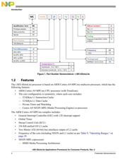
- ・ Teilenummerierungssystem on Seite 3 Seite 4
- ・ Blockdiagramm on Seite 8 Seite 19
- ・ Technische Daten on Seite 14 Seite 17 Seite 18
- ・ Anwendungsbereich on Seite 2 Seite 3 Seite 4 Seite 5 Seite 6
- ・ Elektrische Spezifikation on Seite 17 Seite 18 Seite 19 Seite 20 Seite 21
- ・ Teilenummernliste on Seite 3 Seite 6