
herunterladen
Freescale Semiconductor, Inc.
Data Sheet: Technical Data
Document Number: IMX6SDLIEC
Rev. 5, 06/2015
MCIMX6SxCxxxxxB
MCIMX6SxCxxxxxC
MCIMX6UxCxxxxxB
MCIMX6UxCxxxxxC
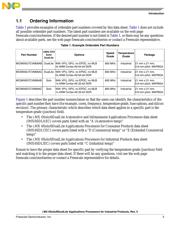
Package Information
Plastic Package
BGA Case 2240 21 x 21 mm, 0.8 mm pitch
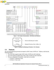
Ordering Information
See Table 1 on page 3
© 2012-2015 Freescale Semiconductor, Inc. All rights reserved.
1 Introduction
The i.MX 6Solo/6DualLite processors represent
Freescale Semiconductor's latest achievement in
integrated multimedia-focused products offering
high-performance processing with a high degree of
functional integration to meet the demands of high-end,
advanced industrial and medical applications requiring
graphically rich and highly responsive user interfaces.
The processors feature Freescale’s advanced
implementation of single/dual ARM
®
Cortex
®
-A9 core,
which operates at speeds of up to 800 MHz. They
include 2D and 3D graphics processors, 1080p video
processing, and integrated power management. Each
processor provides a 32/64-bit
DDR3/LVDDR3/LPDDR2-800 memory interface and a
number of other interfaces for connecting peripherals,
such as WLAN, Bluetooth
®
, GPS, hard drive, displays,
and camera sensors.
i.MX 6Solo/6DualLite
Applications Processors
for Industrial Products
1 Introduction . . . . . . . . . . . . . . . . . . . . . . . . . . . . . . . . . . . .1
1.1 Ordering Information . . . . . . . . . . . . . . . . . . . . . . . .3
1.2 Features . . . . . . . . . . . . . . . . . . . . . . . . . . . . . . . . . .4
1.3 Updated Signal Naming Convention . . . . . . . . . . . .8
2 Architectural Overview . . . . . . . . . . . . . . . . . . . . . . . . . . . .8
2.1 Block Diagram . . . . . . . . . . . . . . . . . . . . . . . . . . . . .8
3 Modules List . . . . . . . . . . . . . . . . . . . . . . . . . . . . . . . . . . .10
3.1 Special Signal Considerations . . . . . . . . . . . . . . . .20
3.2 Recommended Connections for Unused Analog
Interfaces . . . . . . . . . . . . . . . . . . . . . . . . . . . . . . . .22
4 Electrical Characteristics . . . . . . . . . . . . . . . . . . . . . . . . .22
4.1 Chip-Level Conditions . . . . . . . . . . . . . . . . . . . . . .22
4.2 Power Supplies Requirements and Restrictions. . .32
4.3 Integrated LDO Voltage Regulator Parameters . . .34
4.4 PLL’s Electrical Characteristics. . . . . . . . . . . . . . . .36
4.5 On-Chip Oscillators . . . . . . . . . . . . . . . . . . . . . . . .37
4.6 I/O DC Parameters . . . . . . . . . . . . . . . . . . . . . . . . .38
4.7 I/O AC Parameters . . . . . . . . . . . . . . . . . . . . . . . . .41
4.8 Output Buffer Impedance Parameters . . . . . . . . . .45
4.9 System Modules Timing . . . . . . . . . . . . . . . . . . . . .47
4.10 General-Purpose Media Interface (GPMI) Timing .65
4.11 External Peripheral Interface Parameters. . . . . . . .73
5 Boot Mode Configuration . . . . . . . . . . . . . . . . . . . . . . . .131
5.1 Boot Mode Configuration Pins . . . . . . . . . . . . . . .131
5.2 Boot Device Interface Allocation. . . . . . . . . . . . . .133
6 Package Information and Contact Assignments . . . . . .134
6.1 Updated Signal Naming Convention . . . . . . . . . .134
6.2 21x21 mm Package Information . . . . . . . . . . . . . .134
7 Revision History . . . . . . . . . . . . . . . . . . . . . . . . . . . . . . .159
Verzeichnis
- ・ Abmessungen des Paketumrisses on Seite 20 Seite 33 Seite 134 Seite 135 Seite 136
- ・ Teilenummerierungssystem on Seite 3 Seite 4
- ・ Markierungsinformationen on Seite 4
- ・ Blockdiagramm on Seite 8 Seite 9
- ・ Beschreibung der Funktionen on Seite 101
- ・ Technische Daten on Seite 13 Seite 22 Seite 23 Seite 83 Seite 86
- ・ Anwendungsbereich on Seite 2 Seite 3 Seite 4 Seite 5 Seite 6
- ・ Elektrische Spezifikation on Seite 22 Seite 23 Seite 24 Seite 25 Seite 26
- ・ Teilenummernliste on Seite 3 Seite 7