

herunterladen
6-Lead SOT-23 ADC Driver User Guide
UG-682
One Technology Way • P. O. Box 9106 • Norwood, MA 02062-9106, U.S.A. • Tel: 781.329.4700 • Fax: 781.461.3113 • www.analog.com
6-Lead SOT-23 ADC Driver for the 8-/10-Lead Family
of 14-/16-/18-Bit PulSAR ADC Evaluation Boards
PLEASE SEE THE LAST PAGE FOR AN IMPORTANT
WARNING AND LEGAL TERMS AND CONDITIONS.
Rev. 0 | Page 1 of 8
FEATURES
Enables quick breadboarding/prototyping
User defined circuit configuration
Edge-mounted header for easy connections
Standalone power supply for power supply adjustments
COMPATIBLE PulSAR EVALUATION BOARDS
8-lead PulSAR evaluation board
16-bit ADCs: AD7683, AD7684, AD7694
10-lead PulSAR evaluation board
14-bit ADCs: AD7942, AD7946
16-bit ADCs: AD7685, AD7686, AD7687, AD7688, AD7693,
AD7980, AD7983, AD7988-5
18-bit ADCs: AD7690, AD7691, AD7982, AD7984, AD7989-5
GENERAL DESCRIPTION
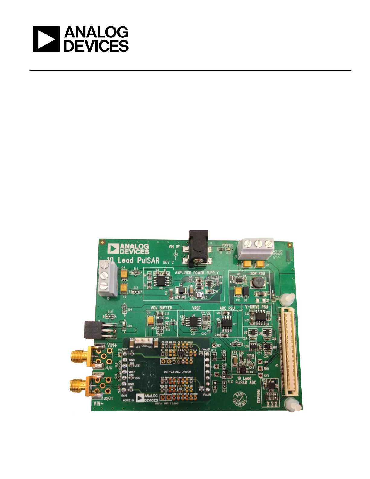
The Analog Devices, Inc., 6-lead SOT-23 ADC driver is used to
evaluate the performance of amplifiers in an SOT package with
the 8-/10-lead family of 14-/16-/18-bit PulSAR® ADC evaluation
boards. This add-on board can easily be inserted on either side
of the ADC evaluation board using the 7-pin header. Figure 1
shows the mounted SOT-23 ADC driver on the ADC evaluation
board. Figure 5 and Figure 6 show the bare SOT-23 ADC driver—
component side and solder side, respectively.
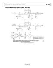
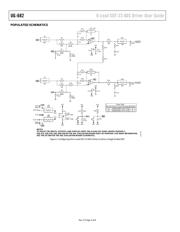
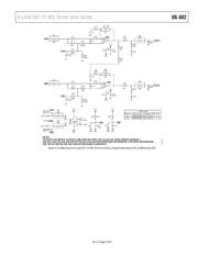
Figure 2 shows the evaluation board schematic. Figure 3 shows
how the user can configure the 6-lead SOT-23 ADC driver to drive
a single-ended ADC. Figure 4 shows how the user can configure
the 6-lead SOT-23 ADC driver to drive a single-ended signal into a
differential ADC. The bill of materials is listed in Table 1.
MOUNTED 6-LEAD SOT-23 ADC DRIVER
12232-001
NOTES
1. TO ROUTE THE INPUTS, OUTPUTS,
AND SUPPLIES ONTO THE 6-LEAD SOT-23 ADC DRIVER PROPERLY, R20, R21, R28, R35, R36,
AND R40 ON THE ADC EV
ALUATION BOARD MUST BE REMOVED. FOR MORE INFORMATION, SEE THE UG-340 FOR THE
ADC EVALUATION BOARD SCHEMATICS.
Figure 1. A 6-Lead SOT-23 ADC Driver Mounted onto a 10-Lead PulSAR ADC Evaluation Board
Verzeichnis