

herunterladen

Rev. 0.2 2/14 Copyright © 2014 by Silicon Laboratories C8051F38x
C8051F38x
C8051F38X DEVELOPMENT KIT USER’S GUIDE
1. Kit Contents
The C8051F38x Development Kit contains the following items:
C8051F380 Target Board
C8051Fxxx Development Kit Quick-Start Guide
AC to DC Power Adapter
USB Debug Adapter (USB to Debug Interface)
USB Cable
CD-ROM
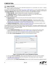
2. Hardware Setup Using a USB Debug Adapter
The target board is connected to a PC running the Silicon Laboratories IDE via the USB Debug Adapter as shown
in Figure 1.
1. Connect the USB Debug Adapter to the DEBUG connector on the target board with the 10-pin ribbon
cable.
2. Connect one end of the USB cable to the USB connector on the USB Debug Adapter.
3. Connect the other end of the USB cable to a USB Port on the PC.
4. Connect the ac/dc power adapter to power jack P1 on the target board.
Use the Reset button in the IDE to reset the target when connected using a USB Debug Adapter.
Remove power from the target board before removing the ribbon cable from the target board. Connecting
or disconnecting the cable when the devices have power can damage the device and/or the USB Debug
Adapter.
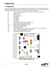
Figure 1. Hardware Setup Using a USB Debug Adapter
Note: The C8051F380 target board has the ability to be powered through the USB cable. To enable the USB-powered mode,
short the pins labeled VBUS and VREGIN on the J8 header. Do not short all 3 pins on the J8 header.
PC
USB
Cable
USB Debug Adapter
AC/DC
Adapter
Target Board
SILICON LABORATORIES
PWR
P1.6
P3.7RESET
Port 4Port 3Port 1
Port 2 Port 0
MCU
Silicon Laboratories
USB DEBUG ADAPTER
Run
StopPower
Verzeichnis