

herunterladen

User's Guide
SNWA011B–May 2010–Revised July 2014
AN-2014 LMH2110 Evaluation Board
General Description
The evaluation board is designed to help the evaluation of the Texas Instruments LMH2110, which is a 45
dB Logarithmic RMS power detector particularly suited for accurate power measurement of modulated RF
signals that exhibit large peak-to-average ratios, that is, large variations of the signal envelope. Such
signals are encountered in W-CDMA and LTE cell phones. The RMS measurement topology inherently
ensures a modulation insensitive measurement.
The device has an RF frequency range from 50 MHz to 8 GHz. It provides an accurate, temperature and
supply insensitive, output voltage that relates linearly to the RF input power in dBm. The LMH2110's
excellent conformance to a logarithmic response enables an easy integration by using slope and intercept
only, reducing calibration effort significantly. The device operates with a single supply from 2.7V to 5V.
The LMH2110 has an RF power detection range from -40 dBm to 5 dBm and is ideally suited for use in
combination with a directional coupler. Alternatively a resistive divider can be used as well.
The device is active for EN = High, otherwise it is in a low power consumption shutdown mode. To save
power and prevent discharge of an external filter capacitance, the output (OUT) is high-impedance during
shutdown.
The LMH2110 power detector is offered in a tiny 6-bump DSBGA package.
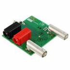
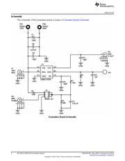
LMH2110 Evaluation Board shows the LMH2110 Evaluation Board.
Basic Operation
The circuit operates with a single supply form 2.7V to 5V and has an RF power detection range from −40
dBm to 5 dBm. The board consist of a single LMH2110 along with external components soldered on a
printed circuit board. External supply voltages and input signals can be applied to the on-board
connectors. The supply voltage is applied with connectors P21 (VDD) and P22 (GND). The RF input
signal is applied by SMA connector P1. This RF signal is applied through an RF generator and is
connected with a 50Ω SMA cable. The detector output can be measured via BNC connector P3.
Configuration
The LMH2110 evaluation board can be configured via jumper settings. The device is active when EN =
High. This can be accomplished by setting the jumper J4 to VDD or by using external control on P4 by
setting the jumper J4 to EN. Since the device has an internal operating voltage of 2.5V, the voltage level
on the enable should not be higher than 3V to prevent damage to the device. Also enable voltage levels
lower than 400 mV below GND should be prevented. In both cases the ESD devices start to conduct
when the enable voltage range is exceeded and excessive current will be drawn. To guarantee a correct
operation a voltage divider formed by R2 and R3 is present on the evaluation board. The absolute
maximum ratings are also exceeded when the enable (EN) is switched to HIGH (from shutdown to active
mode) while the supply voltage is switched off. This situation should be prevented at all times. A solution
to protect the device is the resistor R1 of 1 kΩ in series with the enable input to limit the current.
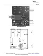
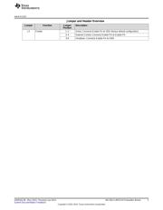
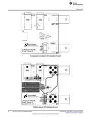
An overview of the various jumper positions on the board is given in Jumper Positions. The settings of
these jumpers and their functions are listed in Jumper and Header Overview.
All trademarks are the property of their respective owners.
1
SNWA011B–May 2010–Revised July 2014 AN-2014 LMH2110 Evaluation Board
Submit Documentation Feedback
Copyright © 2010–2014, Texas Instruments Incorporated
Verzeichnis
- ・ Blockdiagramm on Seite 4
- ・ Beschreibung der Funktionen on Seite 1
- ・ Anwendungsbereich on Seite 9