


herunterladen
Freescale Semiconductor, Inc. reserves the right to change the detail specifications,
as may be required, to permit improvements in the design of its products.
Document Number: MC33883
Rev 10.0, 10/2012
Freescale Semiconductor
Technical Data
© Freescale Semiconductor, Inc., 2007-2012. All rights reserved.
H-Bridge Gate Driver IC
The 33883 is an H-bridge gate driver (also known as a full-bridge
pre-driver) IC with integrated charge pump and independent high and
low side gate driver channels. The gate driver channels are
independently controlled by four separate input pins, thus allowing
the device to be optionally configured as two independent high side
gate drivers and two independent low side gate drivers. The low side
channels are referenced to ground. The high side channels are
floating.
The gate driver outputs can source and sink up to 1.0 A peak
current pulses, permitting large gate-charge MOSFETs to be driven
and/or high pulse- width modulation (PWM) frequencies to be utilized.
A linear regulator is incorporated, providing a 15 V typical gate supply
to the low side gate drivers.
This device powered by SMARTMOS technology.
Features
•V
CC
operating voltage range from 5.5 V up to 55 V
•V
CC2
operating voltage range from 5.5 V up to 28 V
• CMOS / LSTTL compatible I / O
• 1.0 A peak gate driver current
• Built-in high side charge pump
• Under-voltage lockout (UVLO)
• Over-voltage lockout (OVLO)
• Global enable with <10 A Sleep mode
• Supports PWM up to 100 kHz
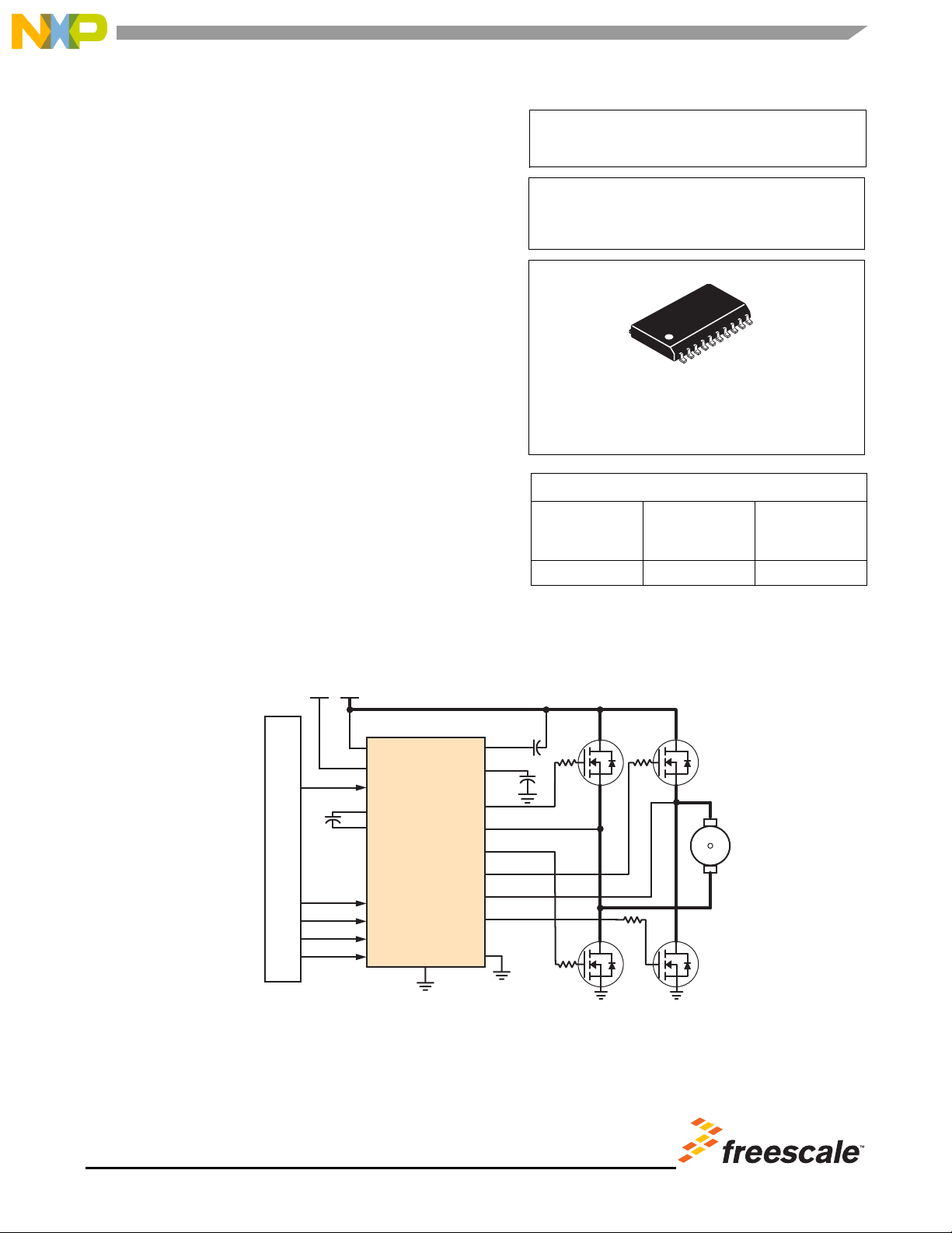
Figure 1. 33883 Simplified Application Diagram
H-BRIDGE GATE DRIVER IC
33883
ORDERING INFORMATION
Device
(Add R2 Suffix for
Tape and Reel)
Temperature
Range (T
A
)
Package
MC33883HEG - 40 °C to 125 °C 20 SOICW
EG SUFFIX (PB-FREE)
98ASB42343B
20-PIN SOICW
MCU
33883
V
BOOST
V
BAT
GND
SRC_HS2
GATE_LS2
CP_OUT
LR_OUT
GATE_HS1
SRC_HS1
GATE_LS1
GATE_HS2
IN_HS1
IN_LS1
IN_HS2
IN_LS2
VCC
VCC2
G_EN
C1
C2
DC
Motor
GND_A
/2
Verzeichnis
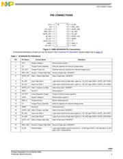
- ・ Konfiguration des Pinbelegungsdiagramms on Seite 3 Seite 10 Seite 11
- ・ Teilenummerierungssystem on Seite 1
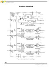
- ・ Blockdiagramm on Seite 2 Seite 12 Seite 18
- ・ Typisches Anwendungsschaltbild on Seite 18
- ・ Beschreibung der Funktionen on Seite 10 Seite 11
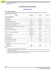
- ・ Technische Daten on Seite 1
- ・ Anwendungsbereich on Seite 18
- ・ Elektrische Spezifikation on Seite 4 Seite 5 Seite 6 Seite 7 Seite 8