
herunterladen

Product
Folder
Sample &
Buy
Technical
Documents
Tools &
Software
Support &
Community
Reference
Design
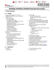
MSP430i2041
,
MSP430i2040
MSP430i2031
,
MSP430i2030
MSP430i2021, MSP430i2020
SLAS887 –AUGUST 2014
MSP430i204x, MSP430i203x, MSP430i202x Mixed-Signal Microcontrollers
1 Device Overview
1.1 Features
1
• Supply Voltage Range 2.2 V to 3.6 V • Clock System
• 16-Bit RISC Architecture, up to 16.384-MHz – 16.384-MHz Internal DCO
System Clock
– DCO Operation With Internal or External
• Power Consumption Resistor
– Active Mode (AM): – External Digital Clock Source
All System Clocks Active
• Up to Four 24-Bit Sigma-Delta Analog-to-Digital
275 µA/MHz at 16.384-MHz, 3.0 V, Flash
Converters (ADCs) With Differential PGA Inputs
Program Execution (Typical)
• Two 16-Bit Timers With Three Capture/Compare
– Standby Mode (LPM3):
Registers Each
Watchdog Timer Active, Full RAM Retention
• Enhanced Universal Serial Communication
210 µA at 3.0 V (Typical)
Interfaces (eUSCIs)
– Off Mode (LPM4):
– eUSCI_A0
Full RAM Retention
• Enhanced UART With Automatic Baud-Rate
70 µA at 3.0 V (Typical)
Detection
– Shutdown Mode (LPM4.5):
• IrDA Encoder and Decoder
75 nA at 3.0 V (Typical)
• Synchronous SPI
• Wake Up From Standby Mode in 1 µs
– eUSCI_B0
• Memories
• Synchronous SPI
– Up to 32KB of Flash Main Memory
• I
2
C
– 1KB of Flash Information Memory
• 16-Bit Hardware Multiplier
– Up to of 2KB of RAM
• Serial Onboard Programming, No External
• Power Management System
Programming Voltage Needed
– Integrated LDO With 1.8-V Regulated Core
• Programmable Code Protection
Supply Voltage
• On-Chip Emulation Module
– Supply Voltage Monitor With Programmable
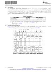
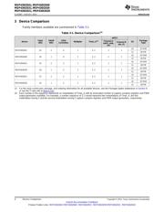
• Family Members are Summarized in Section 3
Level Detection
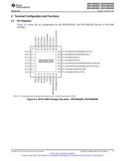
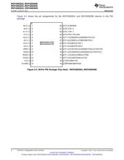
• Available in 28-Pin TSSOP (PW) and 32-Pin
– Brownout Detector
VQFN (RHB) Packages
– Built-in Voltage Reference
• For Complete Module Descriptions, See the
– Temperature Sensor
MSP430i2xx Family User's Guide (SLAU335)
1.2 Applications
• Metering • Power Monitoring and Control
• Submetering • Industrial Sensors
1
An IMPORTANT NOTICE at the end of this data sheet addresses availability, warranty, changes, use in safety-critical applications,
intellectual property matters and other important disclaimers. PRODUCTION DATA.
Verzeichnis
- ・ Konfiguration des Pinbelegungsdiagramms on Seite 5 Seite 48 Seite 50 Seite 51 Seite 52
- ・ Abmessungen des Paketumrisses on Seite 67 Seite 68 Seite 70 Seite 71
- ・ Markierungsinformationen on Seite 64 Seite 67 Seite 68
- ・ Blockdiagramm on Seite 2 Seite 33 Seite 34 Seite 35 Seite 47
- ・ Technische Daten on Seite 14 Seite 15 Seite 16 Seite 17 Seite 18
- ・ Anwendungsbereich on Seite 1 Seite 60 Seite 61 Seite 76