


herunterladen
TMS320DM6467T
www.ti.com
SPRS605C –JULY 2009–REVISED JUNE 2012
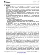
TMS320DM6467T
Digital Media System-on-Chip
Check for Samples: TMS320DM6467T
1 Digital Media System-on-Chip (DMSoC)
1.1 Features
12
– 128K-Byte L2 Unified Mapped RAM/Cache
• High-Performance Digital Media SoC
(Flexible RAM/Cache Allocation)
– 1-GHz C64x+™ Clock Rate
• ARM926EJ-S Core
– 500-MHz ARM926EJ-S™ Clock Rate
– Support for 32-Bit and 16-Bit (Thumb®
– Eight 32-Bit C64x+ Instructions/Cycle
Mode) Instruction Sets
– 8000 C64x+ MIPS
– DSP Instruction Extensions and Single Cycle
– Fully Software-Compatible With C64x /
MAC
ARM9™
– ARM® Jazelle® Technology
– Industrial Temperature Devices Available
– EmbeddedICE-RT™ Logic for Real-Time
• Advanced Very-Long-Instruction-Word (VLIW)
Debug
TMS320C64x+™ DSP Core
• ARM9 Memory Architecture
– Eight Highly Independent Functional Units
– 16K-Byte Instruction Cache
• Six ALUs (32-/40-Bit), Each Supports
– 8K-Byte Data Cache
Single 32-Bit, Dual 16-Bit, or Quad 8-Bit
– 32K-Byte RAM
Arithmetic per Clock Cycle
– 8K-Byte ROM
• Two Multipliers Support Four 16 x 16-Bit
Multiplies (32-Bit Results) per Clock • Embedded Trace Buffer™ (ETB11™) With 4KB
Cycle or Eight 8 x 8-Bit Multiplies (16-Bit Memory for ARM9 Debug
Results) per Clock Cycle
• Endianness: Little Endian for ARM and DSP
– Load-Store Architecture With Non-Aligned
• Dual Programmable High-Definition Video
Support
Image Co-Processor (HDVICP) Engines
– 64 32-Bit General-Purpose Registers
– Supports a Range of Encode, Decode, and
– Instruction Packing Reduces Code Size Transcode Operations
– All Instructions Conditional • H.264, MPEG2, VC1, MPEG4 SP/ASP
– Additional C64x+™ Enhancements • 150-MHz Video Port Interface (VPIF)
• Protected Mode Operation – Two 8-Bit SD (BT.656), Single 16-Bit HD
(BT.1120), or Single Raw (8-/10-/12-Bit) Video
• Exceptions Support for Error Detection
Capture Channels
and Program Redirection
– Two 8-Bit SD (BT.656) or Single 16-Bit HD
• Hardware Support for Modulo Loop
(BT.1120) Video Display Channels
Operation
• Video Data Conversion Engine (VDCE)
• C64x+ Instruction Set Features
– Horizontal and Vertical Downscaling
– Byte-Addressable (8-/16-/32-/64-Bit Data)
– Chroma Conversion (4:2:2↔4:2:0)
– 8-Bit Overflow Protection
• Two Transport Stream Interface (TSIF) Modules
– Bit-Field Extract, Set, Clear
(One Parallel/Serial and One Serial Only)
– Normalization, Saturation, Bit-Counting
– TSIF for MPEG Transport Stream
– Compact 16-Bit Instructions
– Simultaneous Synchronous or
– Additional Instructions to Support Complex
Asynchronous Input/Output Streams
Multiplies
– Absolute Time Stamp Detection
• C64x+ L1/L2 Memory Architecture
– PID Filter With 7 PID Filter Tables
– 32K-Byte L1P Program RAM/Cache (Direct
– Corresponding Clock Reference Generator
Mapped)
(CRGEN) Modules for System Time-Clock
– 32K-Byte L1D Data RAM/Cache (2-Way Set-
Recovery
Associative)
1
Please be aware that an important notice concerning availability, standard warranty, and use in critical applications of
Texas Instruments semiconductor products and disclaimers thereto appears at the end of this data sheet.
2All trademarks are the property of their respective owners.
PRODUCTION DATA information is current as of publication date. Products conform to
Copyright © 2009–2012, Texas Instruments Incorporated
specifications per the terms of the Texas Instruments standard warranty. Production
processing does not necessarily include testing of all parameters.
Verzeichnis
- ・ Konfiguration des Pinbelegungsdiagramms on Seite 23 Seite 102 Seite 105 Seite 110 Seite 112
- ・ Abmessungen des Paketumrisses on Seite 349
- ・ Blockdiagramm on Seite 5 Seite 142 Seite 144 Seite 145 Seite 207
- ・ Typisches Anwendungsschaltbild on Seite 311
- ・ Technische Daten on Seite 14 Seite 135 Seite 137 Seite 139 Seite 140
- ・ Anwendungsbereich on Seite 2 Seite 352
- ・ Elektrische Spezifikation on Seite 14 Seite 132 Seite 137 Seite 138 Seite 139