


herunterladen
User's Guide
SLVU690–April 2012
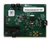
TPS62366AEVM-757
This user’s guide describes the characteristics, operation, and use of the Texas Instruments TPS62366A
evaluation module (EVM). This EVM is designed to help the user easily evaluate and test the operation
and functionality of the TPS62366A. The EVM converts a 2.5-V to 5.5-V input voltage to a regulated
output voltage that delivers 4 A. The output voltage is programmable via the I2C interface in 10-mV steps
between 0.5V and 1.77V. This user’s guide includes setup instructions for the hardware, printed-circuit
board layouts for the EVM, a schematic diagram, a bill of materials, and test results for the EVM.
Contents
1 Introduction .................................................................................................................. 2
2 Setup ......................................................................................................................... 3
3 Software Setup and Operation ............................................................................................ 6
4 Circuit Use and Modifications ............................................................................................. 8
5 Test Results ................................................................................................................ 10
6 Board Layout ............................................................................................................... 15
7 Schematic and Bill of Materials .......................................................................................... 18
List of Figures
1 TPS62366A Software Main Panel........................................................................................ 6
2 Efficiency vs Input Voltage ............................................................................................... 10
3 Efficiency vs Output Current ............................................................................................. 10
4 Load Regulation (Forced PWM Mode) ................................................................................. 10
5 Line Regulation ............................................................................................................ 10
6 Start-up (V
IN
= 3.6V, V
OUT
= 1.2V, I
OUT
= 2A) ........................................................................... 11
7 Shutdown (V
IN
= 3.6V, V
OUT
= 1.2V, I
OUT
= 0, active output capacitor discharge enabled) ....................... 11
8 Output Voltage Ripple (V
IN
= 3.6V, V
OUT
= 1.2V, I
OUT
= 4A)........................................................... 12
9 Input Voltage Ripple (V
IN
= 3.6V, V
OUT
= 1.2V, I
OUT
= 4A)............................................................. 12
10 Load Transient Response (V
IN
= 3.6V, V
OUT
= 1.2V, I
OUT
= 1A to 2A step)......................................... 13
11 Thermal Performance (V
IN
= 3.6V, V
OUT
= 1.2V, I
OUT
= 4A)........................................................... 14
12 Assembly Layer............................................................................................................ 15
13 Top Layer................................................................................................................... 16
14 Layer 2...................................................................................................................... 16
15 Layer 3 ..................................................................................................................... 17
16 Bottom Layer............................................................................................................... 17
17 TPS62366AEVM-757 Schematic........................................................................................ 18
List of Tables
1 Performance Specification Summary..................................................................................... 2
2 Default Jumper Settings.................................................................................................... 5
3 TPS62366A Solution Required Components.......................................................................... 19
4 TPS62366AEVM-757 Evaluation Components........................................................................ 19
VeriSign is a trademark of VeriSign, Inc.
All other trademarks are the property of their respective owners.
1
SLVU690–April 2012 TPS62366AEVM-757
Submit Documentation Feedback
Copyright © 2012, Texas Instruments Incorporated
Verzeichnis