


herunterladen

User's Guide
SLVU878–February 2013
4.5-V to 18-V Input, Dual (6.5-A and 3.5-A) Synchronous
Step-Down Converter With I
2
C Controlled VID and Current
Sharing Evaluation Module
This document is provided with the TPS65276V PMIC evaluation module (EVM) as a supplement to the
TPS65276V datasheet. This user's guide includes the schematic, hardware setup, software installation
and bill of materials (BOM).
Contents
1 Introduction .................................................................................................................. 2
2 Background .................................................................................................................. 2
3 TPS65276V Schematic ..................................................................................................... 3
4 Board Layout ................................................................................................................ 4
5 Bench Test Setup Conditions ............................................................................................. 7
5.1 Header Description and Jumper Placement .................................................................... 7
5.2 Hardware Requirement ............................................................................................ 8
5.3 Hardware Setup .................................................................................................... 8
5.4 Installing Software ................................................................................................. 9
5.5 Software Operation ............................................................................................... 10
6 Power-Up Procedure ...................................................................................................... 11
7 TPS65276V EVM Bill of Materials ....................................................................................... 12
List of Figures
1 TPS65276V Schematic..................................................................................................... 3
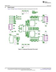
2 Component Placement (Top Layer) ...................................................................................... 4
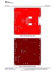
3 Board Layout (Top Layer).................................................................................................. 5
4 Board Layout (Second Layer) ............................................................................................. 5
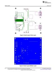
5 Board Layout (Third Layer) ................................................................................................ 6
6 Board Layout (Bottom Layer).............................................................................................. 6
7 Header Description and Jumper Placement............................................................................. 7
8 USB Interface Adapter Quick Connection Diagram .................................................................... 9
9 Screen Capture of TPS65276V Software GUI Interface ............................................................. 10
List of Tables
1 Summary of Performance.................................................................................................. 2
2 Input/Output Connection ................................................................................................... 7
3 Jumpers and Switches ..................................................................................................... 8
4 TPS65276V EVM Bill of Materials....................................................................................... 12
Windows, Microsoft, Internet Explorer are registered trademarks of Microsoft Corporation.
VeriSign is a trademark of VeriSign, Inc.
1
SLVU878–February 2013 4.5-V to 18-V Input, Dual (6.5-A and 3.5-A) Synchronous Step-Down
Converter With I
2
C Controlled VID and Current Sharing Evaluation Module
Submit Documentation Feedback
Copyright © 2013, Texas Instruments Incorporated
Verzeichnis