
herunterladen

1
SLVU847A–April 2013–Revised February 2017
Submit Documentation Feedback
Copyright © 2013–2017, Texas Instruments Incorporated
TPS65381EVM User's Guide
User's Guide
SLVU847A–April 2013–Revised February 2017
TPS65381EVM User's Guide
The TPS65381EVM evaluation module (EVM) helps engineers evaluate the operation and performance of
the TPS65381x-Q1 (TPS65381-Q1 or TPS65381A-Q1) multi-rail power supply for microcontrollers in
safety relevant applications. This document describes how to setup and configure the EVM for operation.
The document also includes the board layout, schematic, and bill of materials (BOM) for the EVM.
Contents
1 Introduction ................................................................................................................... 2
2 TPS65381x-Q1 Description ................................................................................................ 3
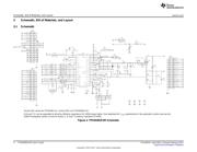
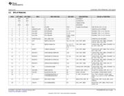
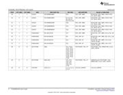
3 Schematic, Bill of Materials, and Layout.................................................................................. 4
4 Setup and Operation....................................................................................................... 12
5 TIGER GUI Software ...................................................................................................... 18
List of Figures
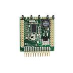
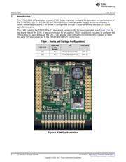
1 EVM Top Board View ....................................................................................................... 2
2 TPS65381EVM Schematic ................................................................................................. 4
3 EVM Top View ............................................................................................................... 7
4 EVM Bottom View ........................................................................................................... 8
5 Top Assembly Layer ........................................................................................................ 9
6 Bottom Assembly Layer..................................................................................................... 9
7 Top Layer Routing ......................................................................................................... 10
8 Layer 2 (AGND) Routing .................................................................................................. 10
9 Layer 3 Routing............................................................................................................. 11
10 Layer 4 Routing............................................................................................................. 11
11 WD Timing .................................................................................................................. 15
12 Start-Up Screen ............................................................................................................ 16
13 After Clicking IGN, Device Has Started, I
q
is About 30 mA, Device is in Diagnostic Mode ...................... 16
14 Clear ERR Fail and WD Fail Flags ...................................................................................... 17
15 Clear DIAG EXIT MASK = Device is in Active Mode.................................................................. 17
16 Set ENABLE_DRV and Read Back Pin Level ENDRV ............................................................... 18
List of Tables
1 Device and Package Configurations ...................................................................................... 2
2 EVM Connectors ........................................................................................................... 12
3 EVM Voltages............................................................................................................... 13
4 EVM Jumper................................................................................................................ 13
5 EVM Test Points............................................................................................................ 14
Trademarks
PowerPAD is a trademark of Texas Instruments.
Verzeichnis