
herunterladen

User's Guide
SLAU605–December 2014
TVB1440 EVM
This document describes how to use and configure the TVB1440 EVM, along with recommendations for
system hardware implementation. These recommendations are only guidelines and it is designer’s
responsibility to consider all system characteristics and requirements. The engineers should refer to the
datasheet (SLASE51) for technical details such as device operation, terminal description, and so forth.
Contents
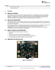
1 Overview...................................................................................................................... 2
1.1 What is the TVB1440? ............................................................................................. 2
1.2 What is the TVB1440 EVM? ...................................................................................... 2
1.3 What is Included in the TVB1440 EVM?......................................................................... 2
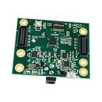
1.4 What Does This EVM Look Like? ................................................................................ 2
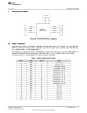
2 Hardware Description ....................................................................................................... 3
2.1 Video Connectors................................................................................................... 3
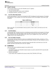
2.2 Local I
2
C Access.................................................................................................... 5
2.3 Enable/Reset........................................................................................................ 5
2.4 Power................................................................................................................. 6
2.5 SW2 DIP Switch Configuration.................................................................................... 7
3 Quick Start Guide............................................................................................................ 7
4 References ................................................................................................................... 7
5 EVM Bill of Materials (BOM) ............................................................................................... 8
6 EVM Schematics............................................................................................................. 9
7 EVM Layout................................................................................................................. 15
List of Figures
1 TVB1440 EVM ............................................................................................................... 2
2 TVB1440 EVM Block Diagram............................................................................................. 3
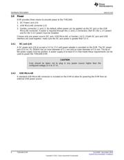
3 TVB1440 EVM Mechanical Drawing ...................................................................................... 4
4 TVB1440 EVM Schematic (1 of 6) ........................................................................................ 9
5 TVB1440 EVM Schematic (2 of 6)....................................................................................... 10
6 TVB1440 EVM Schematic (3 of 6)....................................................................................... 11
7 TVB1440 EVM Schematic (4 of 6)....................................................................................... 12
8 TVB1440 EVM Schematic (5 of 6)....................................................................................... 13
9 TVB1440 EVM Schematic (6 of 6)....................................................................................... 14
10 Layer 1 (Top) ............................................................................................................... 15
11 Layer 2 (GND) .............................................................................................................. 15
12 Layer 3 (Power) ............................................................................................................ 16
13 Layer 4 (Power) ............................................................................................................ 16
14 Layer 5 (GND) .............................................................................................................. 17
15 Layer 6 (Bottom)............................................................................................................ 17
List of Tables
1 Video Input Connector (J1)................................................................................................. 3
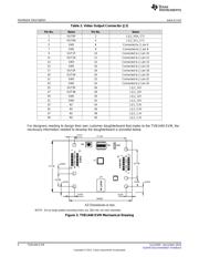
2 Video Output Connector (J2)............................................................................................... 4
3 JMP1 Pin-out................................................................................................................. 5
1
SLAU605–December 2014 TVB1440 EVM
Submit Documentation Feedback
Copyright © 2014, Texas Instruments Incorporated
Verzeichnis