
herunterladen
1
®
FN8146.1
CAUTION: These devices are sensitive to electrostatic discharge; follow proper IC Handling Procedures.
1-888-INTERSIL or 1-888-468-3774
| Intersil (and design) is a registered trademark of Intersil Americas Inc.
Copyright Intersil Americas Inc. 2005. All Rights Reserved
All other trademarks mentioned are the property of their respective owners.
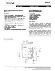
X60250
Micro Power Programmable Voltage
Reference
FEATURES
• 1.25V 1.0%, 20ppm/°C Tempco Reference
• Adjustable to ±0.25% Over the 0 to 1.25V Range
• 8 bit, 100kΩ XDCP on-chip
• Programmable Resolution of 4.9mV (255 steps)
• Extra Matched 100kΩ Resistor Available for
Increased Resolution Over a Smaller Range
• 2.7V to 5.5V Supply Range
• 2-Wire Interface for Programming Reference
Setting
• Low Supply Current: 12µA in Normal Mode
• 8-pin TSSOP Package
• Programmable Reference
• NV Memory
• Pb-Free Plus Anneal Available (RoHS Compliant)
PROGRAMMABLE VOLTAGE
REFERENCE APPLICATIONS
• Sensor Bias
• Variable DAC reference
• Linear Voltage Regulators
• DC/DC converters
• Voltage comparators
• Motor controllers
• Amplifier biasing
DESCRIPTION
The Intersil X60250 combines a temperature
compensated voltage reference with a Intersil Digitally
Controlled Potentiometer (XDCP) to provide a precision
adjustable reference with a range of 0.0V to 1.25V. The
device includes a serial bus interface to enable in-circuit
programming of the reference voltage.
The XDCP contains a resistor chain with 255 taps to
provide 8 bits of digital adjustment to the reference
voltage. Non-volatile storage retains the digital wiper
setting, for permanent reference programming. An
additional matched 100kΩ resistor is available to
increase resolution of the output voltage while retaining
accuracy.
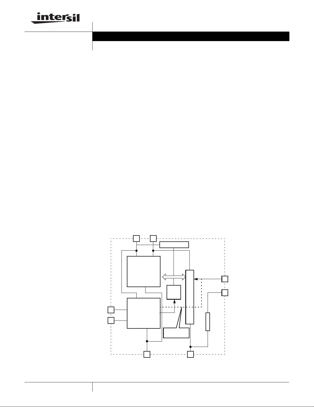
IC BLOCK DIAGRAM
V
CC
V
REFOUT
SCL
SDA
GND V
REFL
V
OUT
R
1
100K
100kΩ
1.25V
Reference
Serial
Interface
EE
PROM
256 Tap DCP
Pwr On Recall
Digital Wiper
Control
Data Sheet September 14, 2005
Verzeichnis
- ・ Konfiguration des Pinbelegungsdiagramms on Seite 2 Seite 10
- ・ Teilenummerierungssystem on Seite 2
- ・ Markierungsinformationen on Seite 2
- ・ Blockdiagramm on Seite 1
- ・ Beschreibung der Funktionen on Seite 7
- ・ Technische Daten on Seite 5
- ・ Anwendungsbereich on Seite 1 Seite 14
- ・ Elektrische Spezifikation on Seite 13 Seite 14